Future-proof multi-generational living in a courtyard development
"Designing bridges is a multifaceted task that requires the consideration of functional, static-structural, urban planning and design goals." This quote comes from the famous bridge builder Andreas Keil. And it is precisely these challenges he names that came to bear during the extension of the Waal bridge in Dutch Nijmegen. In this article, learn what is so special about this structure, how the planning worked and what challenges the bridge engineers had to overcome.
New Reinforced Concrete Bridge Offers "Room for the Waal"
The original Waal bridge runs into the city of Nijmegen over the river Waal, an arm of the Rhine. It was already constructed between 1931 and 1936. As part of a large-scale floor protection project, Holland is planning to create more flood space for rivers in a total of 30 cities. One of these cities is Nijmegen. This is where the Waal river curves strongly and narrows into a bottleneck, which in the past has repeatedly led to the congestion of water mases.
The sub-project "Room for the Waal", which was implemented between 2013 and 2016, had the following measures, all of which occurred simultaneously:
• relocation of the dike from Lent (district of Nijmegen) inland,
• excavation of an additional arm of the river at eights meters depth and 3.5 km long on the shore side of Lent,
• development of the newly created elongated island, the district of Waalsprong, with attractive apartments, museums and 350 meters of shore promenade.
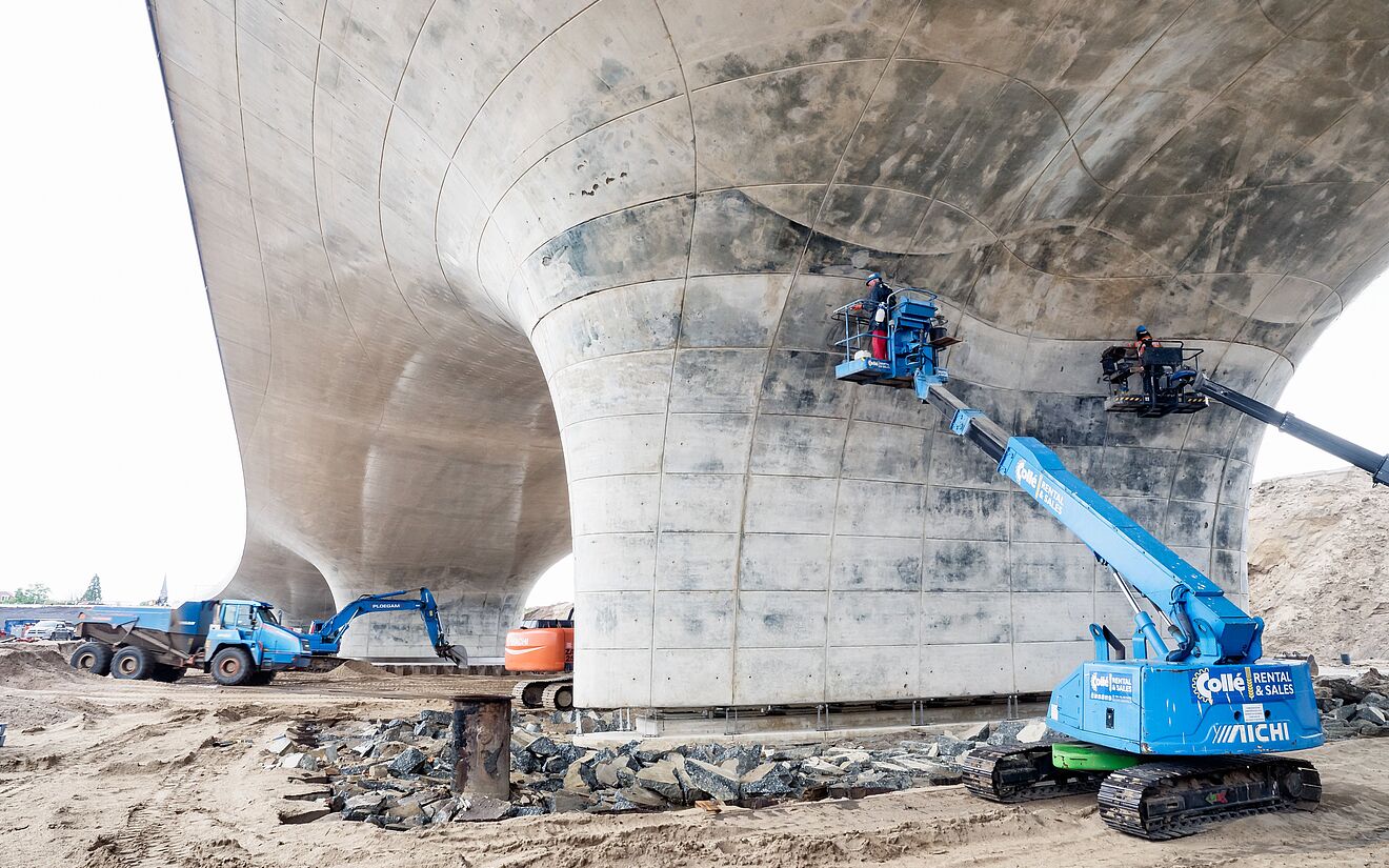
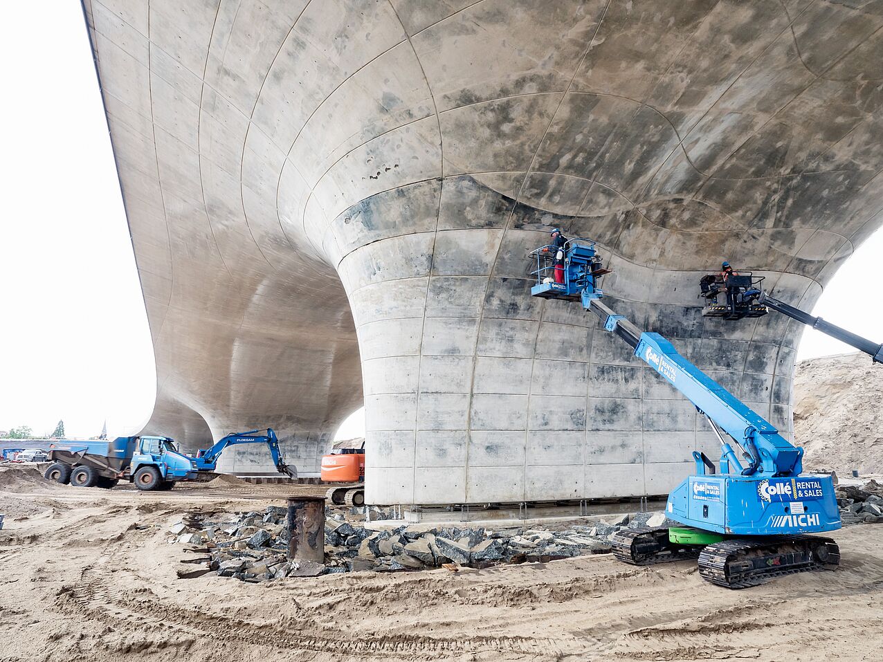
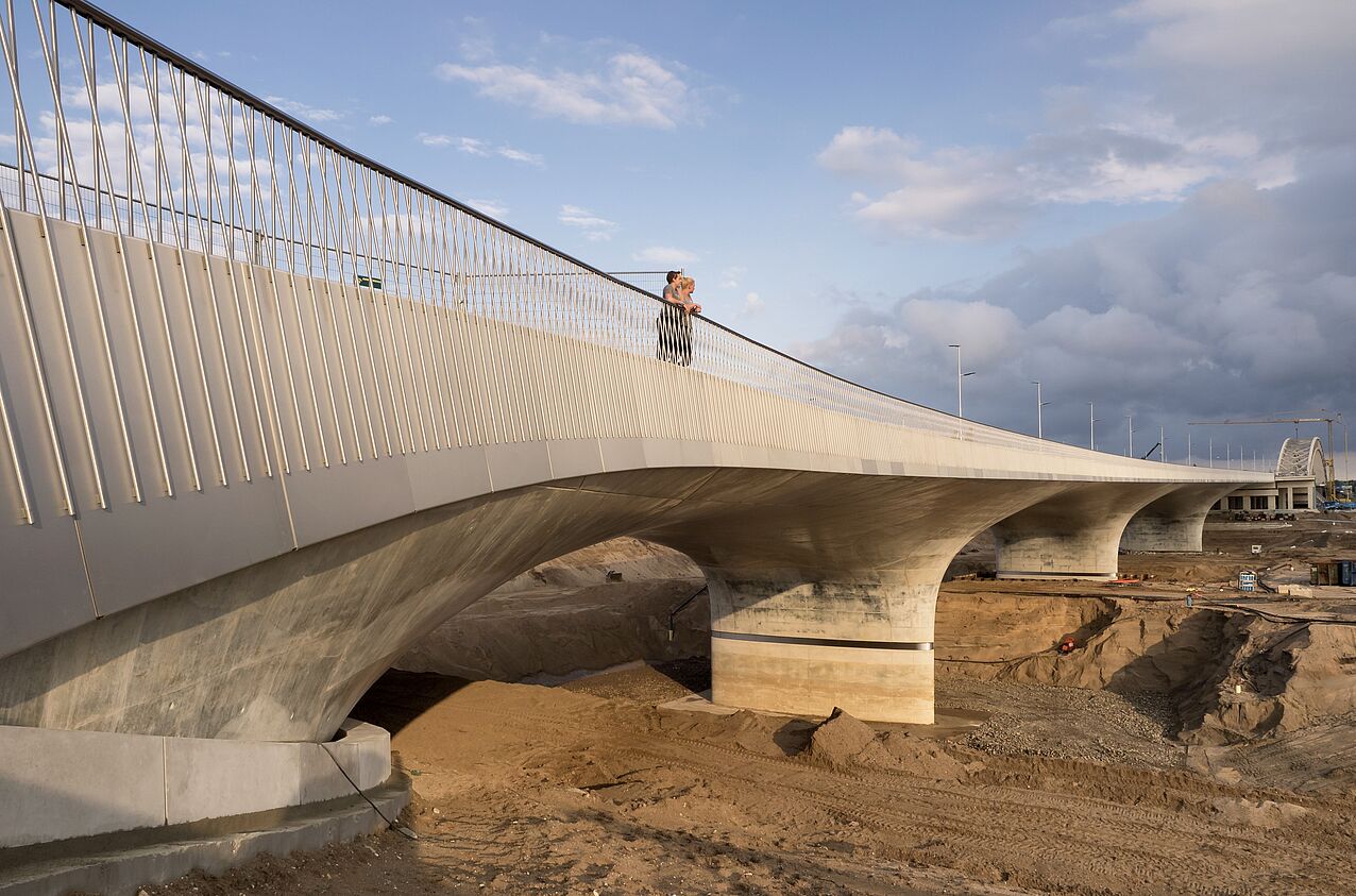
Between this new river island and the district of Lent is now the extended Waal bridge, a spectacular 275-meter long structure with an organic form and hybrid bases. Two techniques of bridge building are combined in the hybrid supporting structures: Construction made of prestressed concrete and steel composite. The extended Waal bridge consists of four tensionedarcs with a width of between 52 and 79 meters as well as a bulwark that serves as a connection member between the historic and new bridge.
Ground-Supported Slabs Provide the Required Load-Bearing Capacity
The architectural firm Zwarts en Jansma is responsible for the bridge construction project. The employees developed a hollow bridge deck that consists of an upper and a lower shell. The upper section is composed of more than 3200 individually modeled shell elements. The lower part acts as a pressure arc, which reduces the necessary reinforcement. A combination of ground-supported slabs and piles ensures the necessary load-bearing capacity.
Planning in SCIA Allows for Transparent Calculations
The extended Waal bridge was created using the softwares ALLPLAN Engineering and SCIA Engineer, a modern program for geometric modeling with different loads. All work flows occur in a BIM environment. Architects first created the 3D model in the ALLPLAN program. They then exported the individual parts of this draft into SCIA via an integration feature. They then extracted the forces in the longitudinal direction and were thus able to implement simple cross-section checks. In this way, they determined the optimal combination between the dimensions of the bridge piles and their number. The calculations remained verifiable at all times.
The Extended Waal bridge as an Outstanding Example of Engineering
As mentioned in the beginning, many challenges need to be taken into consideration when building bridges. This is what happened with the extended Waal bridge: It is functional, because it creates a connection between the newly created river island and the district of Lent. The entire bridge with a length of more than 1,000 meters not only is integrated into the urban planning of Nijmegen, but also into the landscaping. On the static-structural level, engineers developed innovative approaches and not least the architects combined old and new in the design – an outstanding structure of engineering skill.
