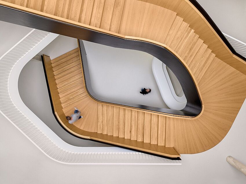
The "treasure hunt" continues: In this second part, Peter Pöppl presents the remaining four of his seven "hidden treasures" in ALLPLAN.
As an ALLPLAN expert, Peter Pöppl knows all the tricks for working efficiently and achieving the best results in the BIM software. Having already highlighted the benefits of visual scripting, automatic wall reinforcement, and the various options for attributing components in Part 1 of his seven "hidden treasures" in ALLPLAN, he now shares the remaining four.
#4 3D curve from axis and gradient
The 3D Curve From Axis And Gradient function makes it possible to create a 3D curve from a 2D axis and a gradient. A gradient is a line that describes the change in height along an axis. This makes it easy to model ramps that adapt to the geometry and requirements of a project.
ALLPLAN users draw a 2D axis that represents the floor plan of their ramp. Lines, circles, arcs, or splines can be used for this. To create a closed ramp, the axis must also be closed. Now draw a gradient that represents the change in height along the axis. The gradient must have the same number of segments as the axis. Finally, select both elements and click OK. The function then generates a 3D curve that represents the contour of the ramp.
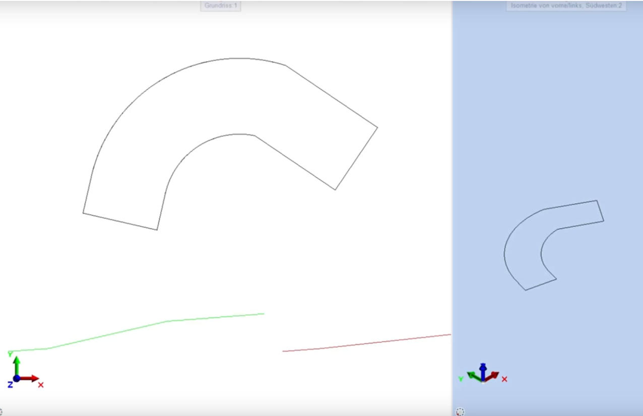
The special feature is that this 3D curve now functions as a path. This can be used not only to create a 3D ramp, but also to lay reinforcement in a curved ramp. For the former, users can use the path Sweep or Loft functions. Sweep creates a 3D ramp from a cross-section and a path, while Loft generates a 3D ramp from several cross-sections along a path. To place reinforcement in a 3D ramp, the Place Along Path function can be used, which generates reinforcement from a cross-section and a path.
#5 Separate bars
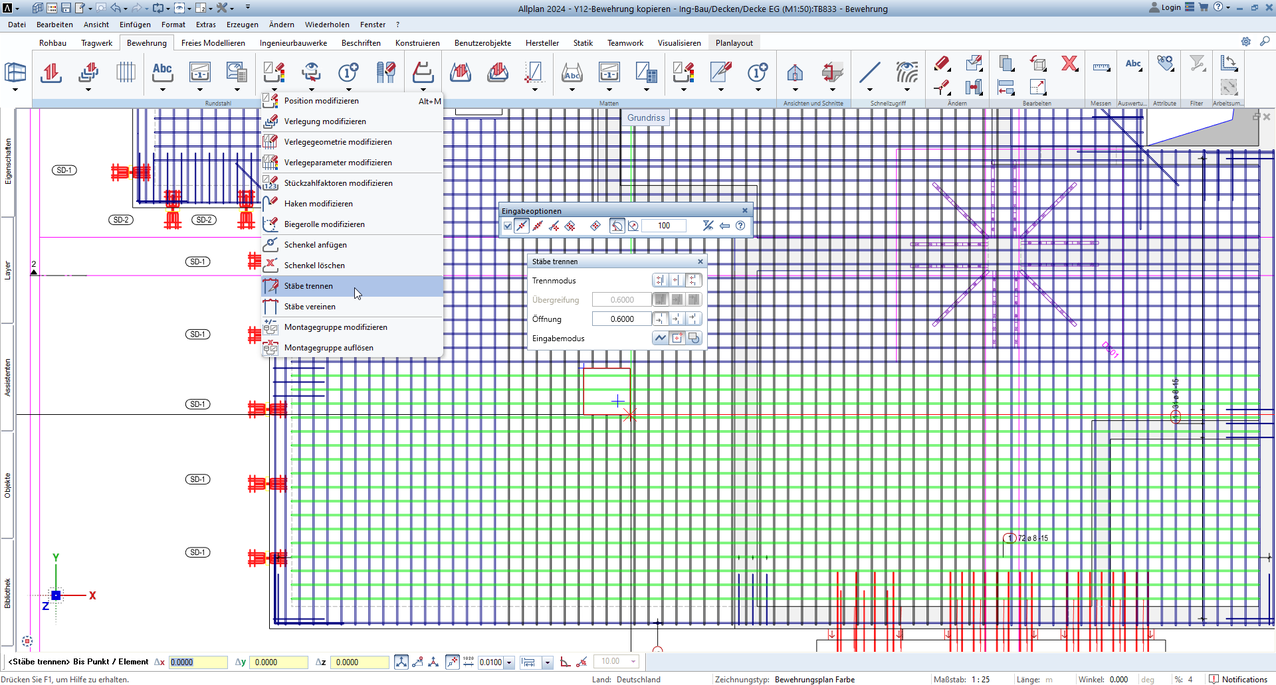
Separate bars is a function that can be used to separate any number of placements in one step. Placements are reinforcements that consist of several bars and are arranged in a specific pattern. ALLPLAN users can use the function to create an overlap, a joint, or an opening along the defined separation. An overlap is an overlapping of two placements that increases the stability and safety of the reinforcement. A joint is a connection of two placements without an overlap, which reduces the geometry and weight of the reinforcement. An opening is a gap between two installations that creates space for other components or openings.
#6 New project management methods
One of the most important new features in ALLPLAN 2024 is the introduction of the "My projects" menu item in the project and resource management area. With this function, projects located in any directory on the computer or network drive can be linked to ALLPLAN. This means that projects no longer have to be saved in a fixed path. This is particularly useful if separate project folders have been created in Windows Explorer, in which all structural analyses, measurements, plans, and other project documents are stored. With ALLPLAN 2024, ALLPLAN projects can now also be saved in these folders and linked via the software. This means that all project data is in one place and can be managed more easily.
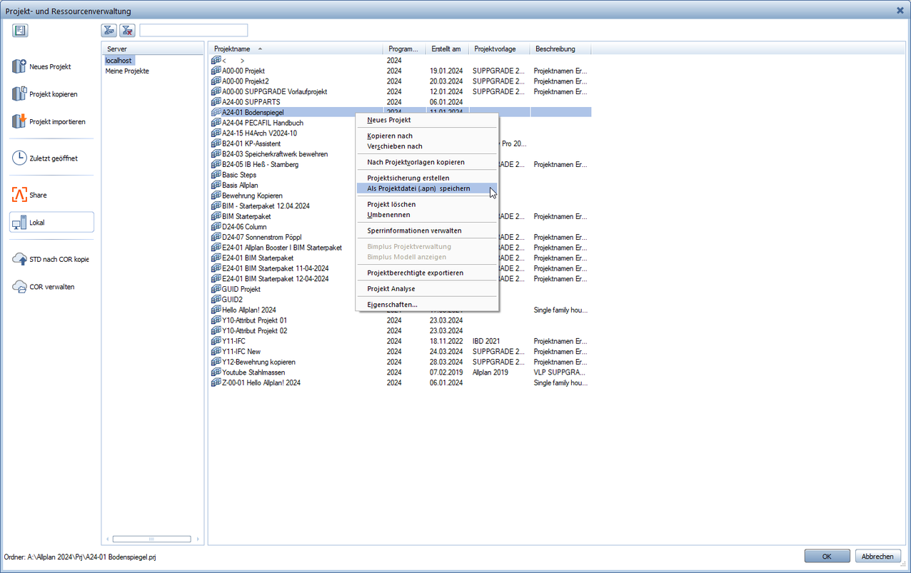
Another new feature in ALLPLAN 2024 is the ability to save, send, and load projects in .apn files. An .apn file is an archive file that contains all the data of a project, such as drawing files, drawings, plans, attributes, layers, etc. With this function, projects can be easily saved, archived, or passed on to other people. ALLPLAN users can create an .apn file from an existing project or import it into a new or existing project.
#7 SUPPARTS®
Built-in parts are components that perform static, sealing, or other important functions in structures, such as punching shear reinforcements, reverse bending connections, shear force dowels, cantilever slab connections, and many more. They must have approval in order to be used on the market. This guarantees that the components meet the necessary requirements.
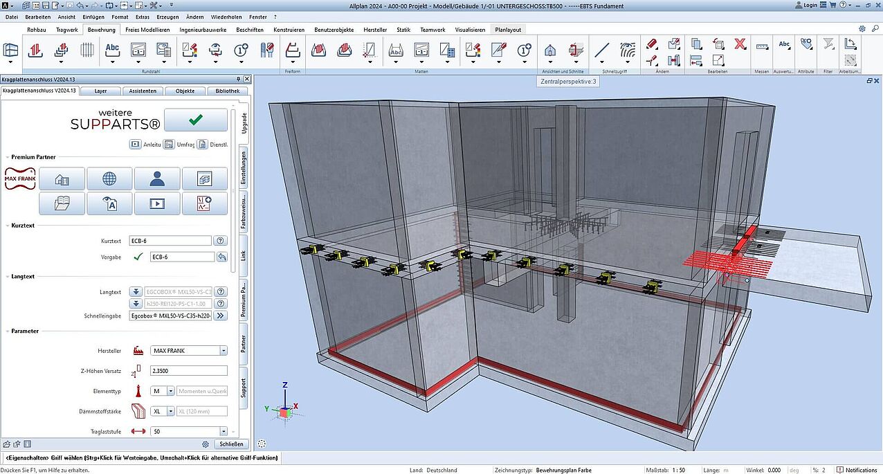
However, built-in components pose a major challenge for structural design. Depending on the manufacturer, they can have different shapes, materials, and designs that affect the structural design. When planning a built-in part, the manufacturer and product must therefore also be specified so that the structural analysis can approve the design. In plans and documents, these are then always described as "or equivalent" in order to also permit built-in parts of a different origin. However, the latter would require a new design, which is time-consuming and expensive.
Another problem is the integration of the digital data of the built-in parts into the CAD software. By default, built-in parts can be created in any CAD program, but this is very time-consuming and entails high logistical requirements. Manufacturers also sometimes offer customers 2D or 3D data, but this is often incompatible, not attributed, or not detailed enough. A cross-component and cross-manufacturer list containing all relevant information is therefore not possible.
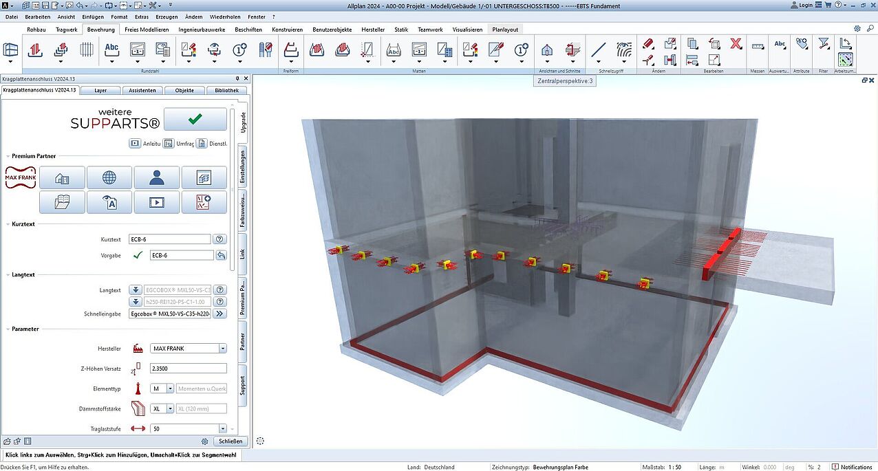
One solution to this problem comes from Peter Pöppl himself: SUPPARTS®. These are fixture generators for ALLPLAN. They can be used to quickly and easily create different fixtures without having to worry about compatibility with different manufacturers. The components created can be evaluated across manufacturers and fixtures and can be modified at any time. The SUPPARTS® solution is available exclusively for ALLPLAN and is completely free of charge for ALLPLAN users.


