Stuttgart 21’s Chalice Supports: Masterpieces of Reinforcement Design
Planning drainage and utility services in a road model can be challenging - or quite simple. A project by CDS Bauingenieure AG in Widnau, Switzerland, shows just how easy it can be.
A road is more than just its surface. Underneath the pavement, there are also pipes for water and electricity supply, wastewater disposal and street drainage, potentially district heating, gas supply, cable TV and telephone or Internet. In some road construction projects, it is therefore also necessary to plan or - in the case of model-based planning - to model these pipelines. A complex task. However, the CDS civil engineers from Heerbrugg know that the modeling of drainage and utility pipelines can also be extremely easy and fast. In the course of renovation work on Büchelstrasse in Widnau, Switzerland, the engineers were not only able to model a complete sewer system and other utilities parametrically in no time at all with the help of the Kanal function in ALLPLAN, but were also able to make complex changes to the model with just a few clicks.
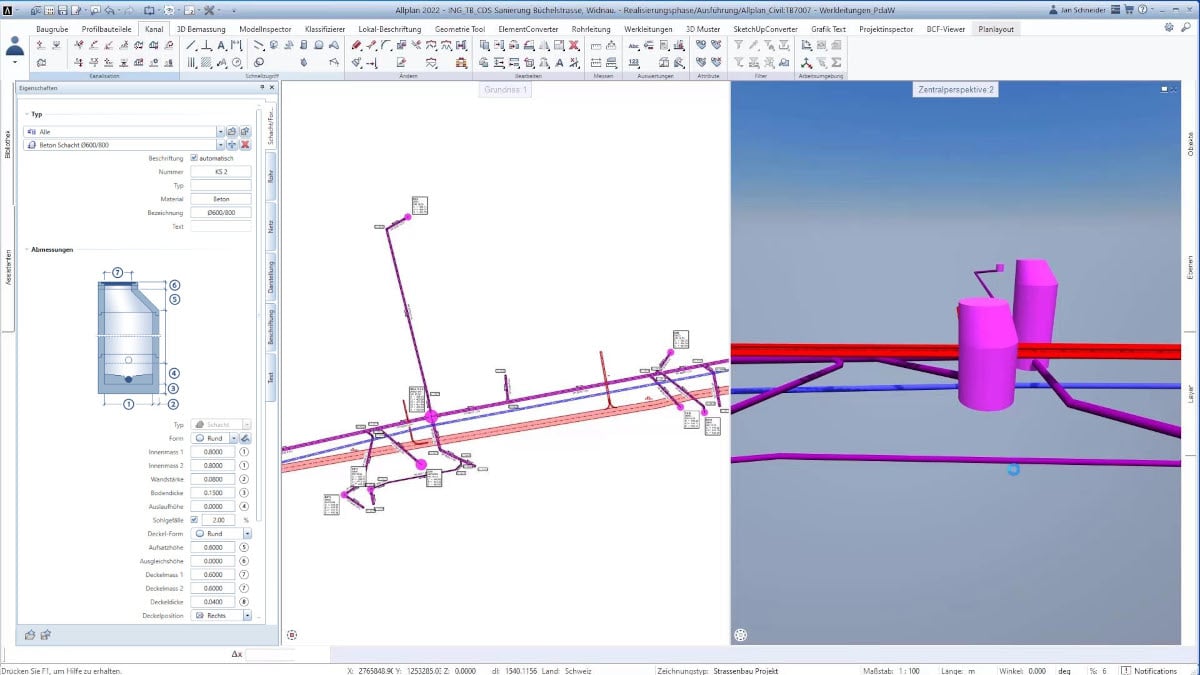
Renewal and extension of pipelines
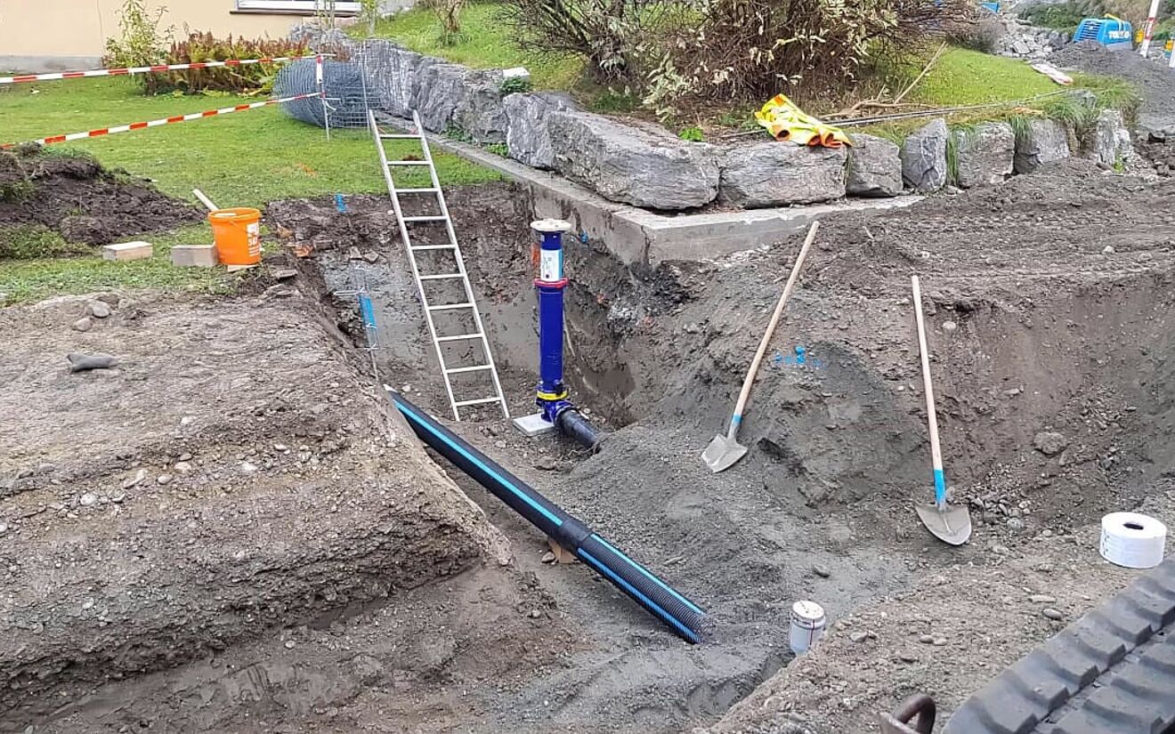
CDS Bauingenieure AG was entrusted with the project management for the renewal of Büchelstrasse in Widnau. Part of this task was the renewal and extension of the service infrastructure for water and electricity supply as well as wastewater disposal. A total of approximately 320 meters of hydrant lines with two new hydrants, 110 meters of water service connections, about 1,500 meters of empty conduits for the electricity supply, ten streetlamps, about 300 meters of sewer pipelines with seven new inspection shafts as well as about 130 meters of drainage pipelines and 17 new street drains were built and installed.
ALLPLAN Kanal function
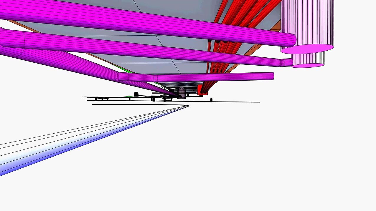
The sewer and service utilities were created parametrically within a very short time using the corresponding ALLPLAN function (Kanal). Thanks to the sewer tool, it was possible to directly change and adjust the outlet height, manhole bottom, diameter or even the type of manhole in the 3D view at any time. At the same time, the entire sewer system could be adapted in the length profile itself in just a few steps. All that is required is to define the area from which the profile is to be created. The profile is then filed next to it, whereupon, for example, the manhole height can be adjusted simply by right-clicking. Thanks to designing in 3D, any collisions can be quickly detected and eliminated during visual collision checks.
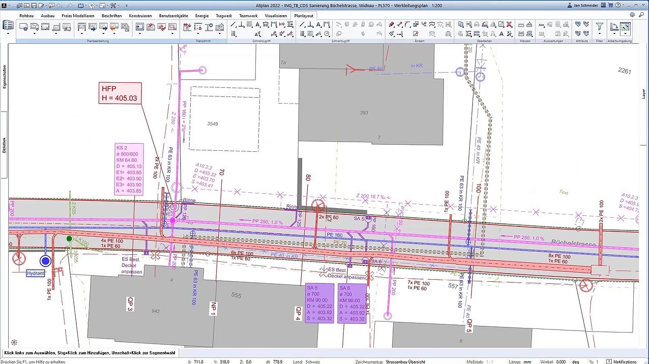
2D plans of the utilities pipelines and sewer systems could be easily derived from the model, as could reports that could be used to evaluate each individual pipe element. The same also applied, for example, to all manhole elements of the sewer network, which could also be read out in reports and divided into groups, for example, which also significantly benefited the execution.
