Future-proof multi-generational living in a courtyard development
Modeling reinforced concrete in 3D sounds difficult – yet, compared to 2D drawing methods, it is actually far easier and quicker with the right detailing software. In just 5 simple steps, you can model, reinforce and detail any structure using advanced 3D modeling software; here’s how:
Step 1: Create the Structural Model
Before you can add reinforcement, you’ll need to create the 3D model of the structure you want to reinforce. For simple structures, a model can be created by adding standard elements such as beams, columns, and walls. For complex structures such as bridges, a 3D model can be created by drawing a section – such as a bridge deck – and extruding it along an alignment (for fixed sections) or sweeping a 3D shape between sections using section strings (for variable sections.) With these methods, even complex shapes can be modeled quickly and easily.
Step 2: Create a Section
Sections can be easily created from the model by specifying where the section should be cut. A 2D section is then created which can be used to place the reinforcement, which will also place it within the 3D model automatically. At the same time the reinforcement can be labelled using the information that is known at that time.
Step 3: Add Reinforcement
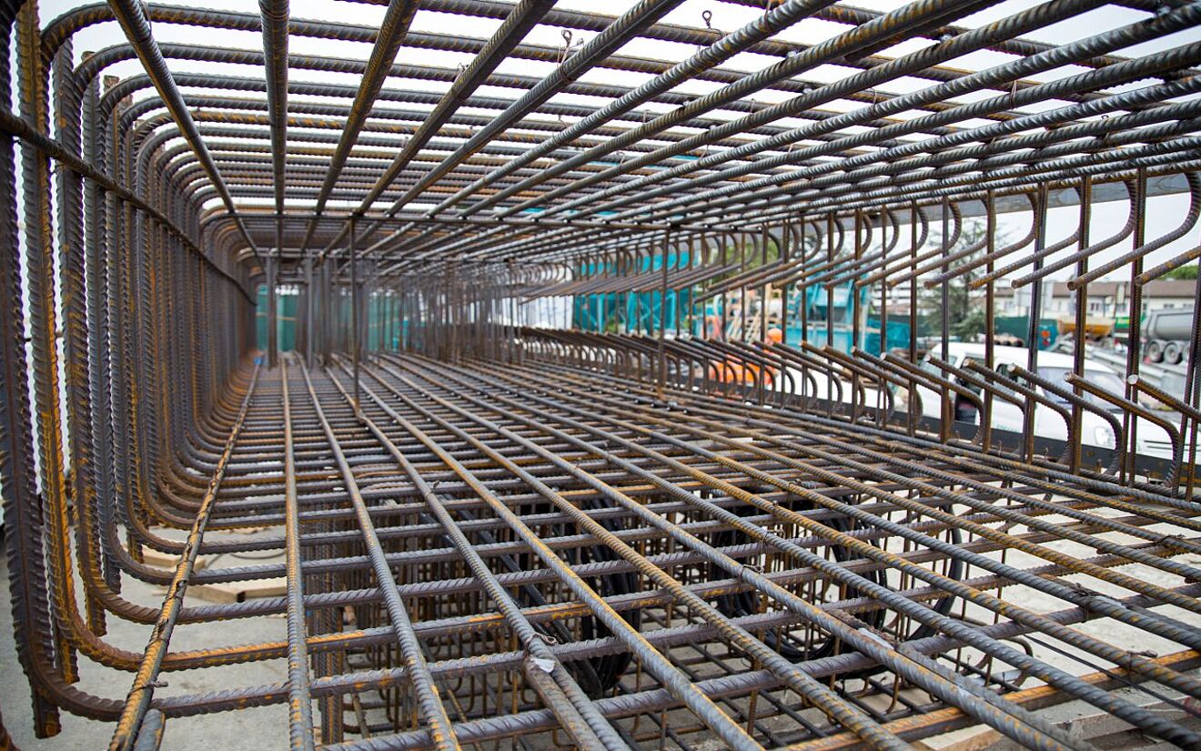
Simple shapes can be reinforced by choosing the bar shape and selecting the element, which can be automatically reinforced at a specified spacing. Alternatively, for complex shapes or longitudinal reinforcement, choose the desired bar shape and then draw where the reinforcement is to be located on the section. The reinforcement is placed automatically in both the 2D and 3D views. To replicate the reinforcement along the element, use the extrude tool (for fixed bar shapes) or the sweep tool (for varying bar shapes or multiple shapes with different paths.) Specific edges can be used to control the variation in bar shapes for the desired result. Mark numbers, number of bars, diameter, cover, hook angle and length can all be varied in the properties box. As bar information becomes available (spacing, number etc). the label (if placed in step 2) is automatically updated.
Step 4: Modify Bar Placements
Bar placement can be modified by selecting a group of bars and amending the spacing to account for variable bar spacing along an element. If a label was placed in step 2 then any modifications to the bar placement are automatically reflected in the label.
Step 5: Add Labels and Schedules
If no label was placed in the earlier steps then one can be placed now using various styles. All the bar information can be conveyed in the details. A bar bending schedule to the chosen detailing code can be generated and placed on the drawing, printed out or even sent to bending machine file.
And that’s it – it is that simple to reinforce structures using 3D rebar software such as ALLPLAN Engineering. Register for our webinar and see the advantages of 3D Reinforcement Modelling for your Engineering Project.


